Me & My partner

Multisim
State Graph, Transition Table, and Boolean Algebra
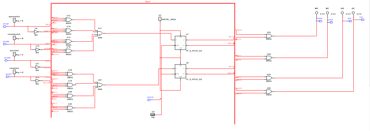
Qa and Qb represent the binary of each state for example state 3 is 11. The four input variables are OS, CS, OL, CL. These are what is used to in the PLD design for the PLD chip to tell it to open, close, and stop. Then there is also the variables MO, MC, GO, GC these are used to create the logic to allow the motor to start opening the gate and closing the gate and tell when it’s completely closed or open.
Conclusion
During this project we had to use the information given to use to create our PLD design in Multisim that later be used to help create the bread board. The bread board is used to wire the "toll booth arm" that would start to move when we pressed a button. One of the buttons would cause it to start to open up until it hit the limit switch that would force it to stop and the other one caused it to close until it hit the other limit switch.
